Category

Theme images by Storman. Powered by Blogger.
Best viewed in Google Chrome

Labels

Labels

Advertisement

Popular Posts

Services

Showing posts with label Ironmaking. Show all posts

Direct Reduction (DR) Processes - First No Coke Option for Iron Making

- No comments
19-Dec-2009

The first no coke method of iron making units is Direct Reduction (DR Process). Direct reduction processes can be divided into those using non-coking coal (as in rotary kiln and rotary hearth furnace based processes) and those using natural gas (as in shaft furnace, fluidized bed furnace, and fixed bed furnace based processes). DR processes using coal have been found to be more suitable in areas, which have local sources of coal and ore but no natural gas. On the other hand in gas-rich areas, gas-based DR (larger in size and more energy efficient) is the automatic choice.

A large number of DR (direct reduction) processes are available today, which can be grouped as follows:
  • Coal based direct reduction (DR processes) using rotary kilns such as SL/RN, DRC, TDR, Jindal, Codir, Accar, SIIL and OSIL. 
  • Coal based direct reduction (DR processes) using rotary hearth furnaces such as Fastmet, Inmetco, Circofer and Sidcomet etc. 
  • Batch type gas based processes using retorts - HyL I. 
  • Continuous processes in a shaft furnace using reformed natural gas as the reductant such as Midrex and HyL III. 
  • Gas based processes using a fluidized bed - Fior, Finmet, Circored.  
  • Special processes for treating waste oxides such as Primus using a multi-hearth furnace.
We have described most of these DR (Direct Reduction) processes separately and individually in this Blog since, it will be too lengthy to put all of them at one place. To know more about each of the DR processes simply type the name of the process in the search box placed near the top of this Blog and search. Alternatively you may select and click on the name of the process from the list of KEYWORDS given in the sidebar.                 

ZERO Waste Steel Shop - The Most Innovative Metallurgical Process

- No comments
28-Nov-2009

The ongoing boom in the iron and steel industry combined with scarcity in raw material supply, their availability has caused a dramatic increase of prices for raw materials and steel roducts. The whole chain of production from front-end side of iron making up to the finishing stage of steel products has to be observed and optimized continuously by introducing highly efficient new technologies, tools, and emission and residue free, environment-friendly processes for production of high value steel products. Among the various innovative iron making processes like Midrex, COREX®, FINEX®, Finmet, Fastmet, Romelt, Primus etc.

ZEWA (Zero Waste) is one such process. Here we are going to discuss in brief about the background and some features of ZEWA process.ZEWA (Zero Waste) is a new metallurgical process which converts blends of industrial waste materials and residues into hot metal and mineral products such as Hydraulic Binders for cement production, metallurgical powders for desulphurization practices and materials suitable for road construction. ZEWA (Zero Waste) process involves high temperature smelting reduction (SR) operations which are carried out in a specially designed, electrically operated reactor.
A demonstration plant with all necessary auxiliary facilities was erected at the Vitkovice Steel Works in the Czech Republic. An earlier report says that it took eleven test campaigns to prove the technical and economical feasibility of the process with respect to the generation of hot metal and useful mineral products from the residues of carbon and stainless steel production.
ZEWA (Zero Waste) Process - A Background
The basis for the development of the ZEWA (Zero Waste) process was laid at the Central Recherche Metallurgique (Center for Metallurgical Research) in Belgium where a laboratory scale smelting reduction process was developed to convert various residues from Steel Plants into valuable metallic and mineral products. Pilot plant tests using a hollow electrode for the pneumatic injection of residue materials into a furnace were then conducted by CRM, MSFOS (Sweden) and FEhS (German Research Institute) in the framework of the IBPM (Internal By-product Melting) project.
In 2000, Voest Alpine (VAI) teamed up with CRM and a large consortium of partners as part of a multi-national project team supported by the European Union. A process concept based on the previously tested pneumatic injection of residue materials into a furnace via an injection lance was chosen. The partnership within this so-called “Fifth Framework Programme” is as follows:
=> From the steel industry; CRM (project coordinator), VAI, ARCELOR, and Vitkovice Research team.
=> From the cement industry; LAFARGE
=> From the car dismantling industry; the Belgian SME Comestsambre.
=> From the coal industry; the ICPC (Institute for Chemical Processing of Coal, Poland)
This project works with a goal of developing a viable technology for the so-called ZEWA (from Zero-Waste) process and to test it on a demonstration scale. The main task to be carried out was thus the design and erection of a dedicated pilot plant, the performance of the pilot test campaigns and the final evaluation of the ZEWA as the basis for commercialization.   
The Principal of ZEWA (Zero Waste) Process
The ZEWA (Zero Waste) process is based on smelting reduction of suitable blends of basic and acidic residue materials from industrial production as follows:
=> From the steel industry basic steel making slags and dusts, and silica containing residues from scrap handling (mixtures of glass and plastics) in EAF plants;
=> Complementary acidic residues from another industrial sectors, such as fly ash from coal-fired power plants, automotive shredder residues (ASR) or bottom ash from urban incinerators (BI ash).
The main products are the refined slag (or mineral product) with targeted chemical composition, and hot metal or metal product to be recycled for steel production. For the smelting reduction (SR) process carbon based reductant (coke, anthracite, coal etc.) are added to the blend of residue materials. Depending on the raw material and the mineral product, small quantities of stronger reductants like ferro-silicon, or additives such as lime or bauxite, may also be added when necessary. Process dust with high zinc content is recovered in an off gas filtering unit. Targeted mineral products are a Portland clinker substitute for use in cement production and metallurgical powders for use in secondary steel refining units.       
ZEWA (Zero Waste) - The Process Technology
The smelting reduction in ZEWA or Zero Waste process is done in an electrically heated ladle-type furnace which is equipped to allow for top charging of liquid steel making slag and coarse solid materials into the foamy slag bath, and also for the deep pneumatic injection of powdery materials into the hot metal with a lance. Coarse solid materials like solid slags are charged by gravity, via a fibro-feeder or by a chute. Injected powdery materials are mainly steel making dusts, fly ash and reductants. Other features of the ladle include bottom stirring (to enhance mixing and reaction kinetics) and post combustion in the upper part of the slag bath (to recover chemical heat through the partial combustion of the CO from the reduction reactions). The ZEWA (Zero Waste) process technology is quite flexible with regards to the input materials, firstly because it allows for the charging of the liquid slag, and secondly because it can cope with highly variable charging ratios of liquid slag, coarse solids and powdery materials. Dry dusts can be directly used as a raw material. Sludges and other residue materials require only drying and micro granulation. No pelletization or briquetting is necessary, thus reducing the material pre-treatment costs substantially. Because of the filtering effect of thick foamy slag bath, ZEWA technology is also very efficient in terms of lowering dust emissions. Moreover, due to the low thermal losses by radiation from the arc and the metal bath, ZEWA process is very effective in lowering the energy consumption too.             

Primus - A Special DR (Direct Reduction) Process for Treating Waste Oxides using a Multi-hearth Furnace (MHF)

- No comments
28-Nov-2009
About the Primus
The Primus process was developed by Paul Wurth, uses a multi-hearth furnace (MHF). The furnace volume and the number of hearth in any unit are variable and can be adapted to the requirements of the material to be processed. Coal fines and iron oxide fines are charged into the top hearth of the multi-hearth furnace and as per the need coal can also be added in the lower hearths. The furnace is operated at temperatures up to 1100OC. The DRI (direct reduced iron) produced is discharged from the lowest hearth of the furnace at a temperature of 105-115OC.

Primus - Some Features of the Process
=> High quality DRI can be produced using ore fines and low cost pulverized coal as the single energy source.
=> No preparation of the raw materials is required, and metallization level exceeding 95% can be easily achieved.
=> In a stationary state, the Primus process does not require any additional energy supply; burners are only required to preheat the furnace. The high degree of post combustion, the counter-current flow of the off-gas and the relatively low process temperatures, make the Primus process energy-efficient.  
At first, in co-operation with Paul Arbed, Paul Wurth built a pilot plant designed for a throughput of ½ t/h in the steel works of Esch-Belval in Luxembourg. Several trial campaigns were carried out to melt the DRI produced on the basis of iron ore and EAF dust since September 2000. All the trials successfully demonstrated the feasibility of the process on a continuous basis which paved way for the successful implementation of the Primus process later in many other plants.    
Related Articles 

MIDREX - The Most Widely accepted Direct Reduction (DR) Process of Ironmaking

- No comments
2-Oct-2009

Midrex the most widely accepted direct reduction (DR) process of ironmaking in the world was developed by Midland Ross Corporation of Cleveland, USA in 1967 , has the following distinctive features:
Recommended Natural Gas Composition for MIDREX Plants
Components
Vol %
Effects
CH4
C2H6
C3H8
C4H10
+C4 (Hydrocarbon)
CO2
N2
S
75 - 100
0 - 25
0 - 4
0 - 2
0 - 0.5
20 max
20 max
20 ppm.
(max Wt.)
--
--
Above 4% C3H8, water vapour content should be increased.
--

Above 20% CO2, export fuel is produced.
For every 10% of N2, fuel consumption increases by 2%.
Above 20 ppm, carbon deposition on catalyst.

MIDREX Process - Some Features
=> It allows the production of highly metalized DRI (exceeding 92%, see adjacent Table showing typical composition of Midrex DRI) and the carbon content of can be controlled in the range of about 1.0 - 2.0%.
=> Although originally developed for use with high grade pellets, the Midrex shaft furnace is now able to use some amount of lump ores. Optimum process conditions are often obtained by mixing 30-50% of an appropriate type of lump ore with high grade pellets. See adjacent Table showing Physical Characteristics of Pellets and Lump Ores used in the MIDREX Process.  
=> Fuel utilization in Midrex process has steadily decreased from an average of 12.5 - 14 GJ/t of DRI to 9.5 - 10.5 GJ/t. This improvement in energy efficiency has been the result of higher reduction temperatures, enrichment of reduction gas with methane, utilization of in-situ reforming, and pre-heating of the process gas utilizing waste heat from the reformer.
=> Following the advent of in-situ reforming, oxygen carriers from an external source are now not required in the production of reformed gas. Therefore, the investment cost and operating costs of Midrex units have been reduced.
=> The DRI produced is relatively active towards re-oxidation, particularly when moisture is present. Hence it must be deactivated if it is to be stored or transported over a long distance.    
Physical Characteristics of Oxide Feeds
(Pellets and Lump Ores) used in the MIDREX Plants

Pellets
Lump Ores
Screen analysis (wt %)
50 - 31.75 mm
31.75 - 6.3 mm
+ 15 mm
8 - 15 mm
– 8 mm
– 6.3 mm
Bulk Density (t/m3)
Compressive Strength (kg/pellet)
ISO Tumbler Test (wt%)
+ 6.3 mm
– 0.5 mm

--
--
10% max
85% max
5% max
--
2.0 - 2.1
270 min


95% min
4% max

5% max.
93% max.
--
--
--
7% max
2.0 - 2.6
--


--
--

Typical Product Composition of Midrex DRI
Content
Wt %
Fe (total)
Fe (metallic)
Metallization
SiO2
Al2O3
CaO
MgO
S
P
92 -93
84 - 88
93 - 95
2.0 - 3.5
0.5 - 1.5
0.2 - 1.6
0.3 - 1.1
0.005 - 0.015
0.02 - 0.04
Related Articles 

ROMELT - Another No Coke Alternative Smelting Reduction (SR) Process of Ironmaking

- 1 comment
19-Nov-2009
ROMELT - The Process
This process was developed by the Moscow Institute of Steel and Alloys (MISA) in the mid-eighties to produce liquid iron from iron-bearing ores (lumps and fines) as well as waste iron oxides generated in an integrated plant using non-coking coal and oxygen. ROMELT is the only single stage SR process.
Unlike COREX and most other SR processes, the strength of this process is that it is a single stage concept. That is why ROMELT is a robust and simple process, which is also very much environment-friendly, since it operates under a slight negative pressure. As a result the area around a ROMELT plant is extremely clean. However, the process has a few inherent weaknesses being a single stage process, it uses large amounts of coal (1.3 - 1.5 t/thm) as well as oxygen (1100 - 1200 Nm3/thm) and it generates a very rich exit gas, which has to be utilized effectively e.g. in power generation to meet the demand of oxygen plant to make the hot metal production economic.        
ROMELT Process - The Advantages
=> This process can accept iron ore in a wide range of sizes (0 - 20 mm) without any pre-treatment. This would allow operating units to use slimes and other iron-bearing wastes which can be a big advantage for many reasons.
=> Non-cocking coals of size 0 - 20 mm with moisture content less than 10% are acceptable for this process. Although it is preferable to restrict the VM content of the coal up to 20%, higher VM coals can also be used. Then, no separate coal preparation is required.
=> The ROMELT process is capable of achieving fairly high degrees of post-combustion (even more than 70%) of the melter gas (primarily CO and H2) before it leaves the reactor, thus ensuring satisfactory utilization of energy even though it is a single stage process.
=> The quality of ROMELT iron is excellent - Carbon 4%, Silicon 0.6%, Manganese 0.05%, Sulphur 0.04% and temperature 1400 - 1450OC. The process offers particular advantage  in terms of phosphorous in hot metal because in the ROMELT process, instead of 100% phosphorous going to metal (as is the case in Blast furnace), only 60% phosphorous is reported to be in the hot metal while 30% goes to the slag, and 10% forms a part of exit gas.
=> Small scale production of 200000 to 1000000 tpa of hot metal is possible along with flexibility in production. The capacity of the rectangular ROMELT reactor (productivity in the range of 0.95 t/m2 of hearth area) is limited by the penetration of oxygen from the side-wall tuyeres into the bath. Thus, ROMELT unit may be ideal for supplying hot metal in EAF based mini steel plants.
=> The specific investment in a ROMELT plant is not likely to be as high as in many other SR processes because the equipment is simple and easy to operate. For the same reason, the plant availability should be high.

What is FASTMET Process of Ironmaking ?

- No comments
11-Sept-2009
Fastmet The Process Concept and References  
This is a direct reduction process using a Rotary Hearth Furnace (RHF) which was derived from the work done in USA by Midland Ross and Surface Combustion, in the ‘Heat Fast’ process, treated in 1960s. It is a solid reductant based process in which iron ore concentrate, pulverized coal and a binder are mixed together and pelletized. The resulting green pellets are fed either to a drier or directly to a rotary hearth furnace where the pellets are heated to 1250 - 1400OC and reduced to metallic iron. Burners and post-combustion the CO evolved provide the heat required to raise the pellets to the reduction temperature.
The first commercial Fastmet plant was commissioned at the Hirohata Works No.1 of Nippon Steel in April, 2000 and Hirohata Works No.2 in February, 2005 with material processing capacities of 190000 tpa each plant. The second plant established was Kobe’s Steel’s Kakogawa Works started from April, 2001 having a material processing capacity of 16000 tpa.  The Fastmet process has allowed the Kakogawa Works to achieve a zero emission rating of steel mill waste. Waste utilization is the principal application of the Fastmet process in Japan.       
FASTMET Process - Flowchart
Advantages of Fastmet


Some of the advantages of Fastmet process as have been reported are summarized as follows:
=> A wide variety of iron ore as well as steel mill wastes including BF dust, BF Sludge, BOF dust, Sinter dust, EAF dust, mill scale, and etc. can be used as the oxide feed.
=> Elimination of waste disposal cost and landfill liability as wastes is changed to a quality source of iron (DRI).
=> Recovery of Zinc contained in wastes (Zn deriving from scrap) which can be sold to zinc producer. Zinc removal: 95% or higher.
=> A wide variety of energy sources can be utilized including natural gas, LPG, coke oven gas, heavy oil, coke breeze and carbon bearing wastes or pulverized non-coking coal.
=> The short reduction time of less than 12 minutes enables easy plant starting and shut-down, and quick adjustment of production rate.
=> Reclamation of carbon is possible. Carbon contained in dusts will be used as reductant. The carbon content of DRI can be adjusted as per the customer’s requirement.
 Related Articles – 

What is Finmet Process (Technology) of Ironmaking ?

- No comments
9-Sept-2009
What is Finmet ?
Finmet is a fluidized bed iron ore reduction process developed jointly by Fior de Venezuela and Voest Alpine (VAI) of Austria in 1991 based on the original Fior process operated in Venezuela. Two Finmet plants are currently in operation - one 2 Mtpa plant at Puerto Ordaz, Venezuela and another 2 Mtpa plant at Port Headland, Western Australia operated by BHP (now Bluescope).
industry.guru
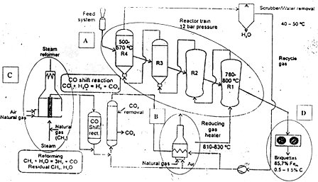
Fig: Flow-chart of Finmet Process
Finmet The Process Concept


The Finmet process uses a train of four fluid bed reactors marked (A) in the adjacent figure with counter-current gas/solids contacting down the reactor train. The feed concentrate (iron ore fines of less than 12 mm size) is charged to the reactor train via a pressurized lock hopper system. The upper lock hopper in this system cycles continuously from ambient to reactor pressure to feed the ore continuously to the reactors maintained at the reactor pressure of 11-13 bars. The feed enters the topmost reactor (R4) where it is pre-heated to 550-570OC by the reducing gas leaving reactor (R3). Pre-heating, dehydration, decrepitation and reduction of hematite to magnetite take place in reactors R4, R3 and R2. The temperature in R1 is around 780-800OC and final reduction to 93% metallization is accomplished in this reactor accompanied by carburization of some of the Fe to iron carbide. The hot fine DRI (at 650OC) is then transported by a sealed system to the briquetting machine (D) to attain a briquette density of around 5 gm/cm3. The product from any Finmet plant is hence, HBI (Hot Briquetted Iron).
The gas required for reduction is a mixture of recycled top gas and fresh reformer make-up gas processed in a standard steam reformer from natural gas. The recycled gas (taken from the top gas leaving R4), is first quenched to 40-50OC and scrubbed in a wet scrubber to remove dust and water. The make-up gas required to balance the gas consumed by the reduction reactions is supplied from a conventional steam reformer system (C).          
Finmet: Advantages and Disadvantages
Some of the advantages and disadvantages of Finmet process of iron making are :
=> It can use very large reserves of iron ore fines as feed stock unlike Midrex and HyL, which can use maximum 5% fines.
=> The output from a Finmet plant is HBI with Fe content varying from 91-94%, carbon 1-1.5% (or 3% maximum), metallization 91-93%.
=> Finmet’s operating pressure is as high as 12 bars to ensure higher degree of metallization. It has been reported that continuous operation at such high pressures has been a major problem in both the Finmet plants.    
Related Articles –